Tuesday, March 31, 2015

Binding Guice bindings to Camel Registry

In the previous post I showed how I was using Commons Configuration with Camel property placeholders using Camel properties functions.

In this post I address the second problem I needed to solve. Binding objects that are bound to a guice injector to the camel registry. Again I should point out that Camel has a guice component that will take care of most of this. But I wanted to experiment with a simple camel context. My camel context is very simple it extends DefaultCamelContext and currently only provides one function, that function allows the injection of the commons configuration and a custom registry.
package com.margic.pihex.camel.context;

import com.google.inject.Inject;
import org.apache.camel.component.properties.PropertiesComponent;
import org.apache.camel.impl.DefaultCamelContext;
import org.apache.camel.spi.Registry;
import org.apache.commons.configuration.Configuration;
import org.slf4j.Logger;
import org.slf4j.LoggerFactory;

/**
 * Created by paulcrofts on 3/27/15.
 */
public class CustomCamelContext extends DefaultCamelContext {

    private static final Logger log = LoggerFactory.getLogger(CustomCamelContext.class);

    @Inject
    public CustomCamelContext(Registry registry, Configuration config) {
        super(registry);
        log.info("Creating Guice Camel Context");
        PropertiesComponent pc = getComponent("properties", PropertiesComponent.class);
        pc.addFunction(new ConfigurationPropertiesFunction(config));
    }
}

This allows me to inject my registry implementation into the constructor of the camel context. The main binding happens in my JNDI registry implementation. The registry takes the guice injector as an argument and then scans the bindings on the injector for annotations. My code does this manually a better option would be to use matchers but the point is still valid.
    @Inject
    public GuiceRegistry(Injector injector) {
        super();
        this.injector = injector;
        bindGuiceObjects();
    }

    /**
     * method to scan injector bindings to register objects
     * annotated with BindCamelRegistry or names
     */
    private void bindGuiceObjects() {
        if (injector != null) {
            log.debug("Binding guice objects to registry");
            Map< key>, Binding> bindings = injector.getBindings();
            for (Key key : bindings.keySet()) {
                if (key.getAnnotationType() == Named.class) {
                    log.debug("Found binding annotated with named. Should be bound to camel registry.");
                    Object object = injector.getInstance(key);
                    Named named = (Named) key.getAnnotation();
                    String name = named.value();
                    bind(name, object);
                }else {
                    javax.inject.Named annotation = (javax.inject.Named)key.getTypeLiteral().getRawType().getAnnotation(javax.inject.Named.class);
                    if(annotation != null) {
                        log.debug("Found object bound with annotation BindCamelRegistry");
                        String name = annotation.value();
                        if (name != null) {
                            Object object = injector.getInstance(key);
                            bind(name, object);
                        }
                    }
                }
            }
        }
    }


This allows me to bind beans in Guice and have them automatically bound to the camel context. I can do the same with other objects using type matchers. For example RouteBuilders. However for now I am happy to manually configure routes during this stage of development.

The following test validates the binding and shows how easy it is to bind objects.

    @Named("myBean")
    static class TestClass{
        // this is just an empty class bound to name myBean for test
    }

    @Test
    public void testBindCamelRegistryAnnotation(){
        // need injector
        Injector injector = Guice.createInjector(new AbstractModule() {
            @Override
            protected void configure() {
                bind(TestClass.class);
            }
        });

        GuiceRegistry registry = new GuiceRegistry(injector);
        Object object = registry.lookupByName("myBean");
        assertNotNull(object);
        TestClass testClass = registry.lookup("myBean", TestClass.class);
        assertNotNull(testClass);
    }

    @Test
    public void testBindCamelRegistryNamedAnnotation(){
        Injector injector = Guice.createInjector(new AbstractModule() {
            @Override
            protected void configure() {
                bind(String.class).annotatedWith(Names.named("testName")).toInstance("My String Value");
            }
        });

        GuiceRegistry registry = new GuiceRegistry(injector);
        String testString = (String)registry.lookup("testName");
        assertEquals("My String Value", testString);

        testString = registry.lookup("testName", String.class);
        assertEquals("My String Value", testString);
    }

Monday, March 30, 2015

Apache Camel Property Placeholders - Commons Configuration in Raspberry Pi

The last set of changes I made were adding Apache Camel to my PiHexJ code. I added support for a camel context running on the Raspberry Pi. It's fairly easy to get Camel running on the Pi however there is a question I guess I need to answer first.

Why add apache camel to my robot?

There are a number of reasons why I chose to add Camel to the Robot's software stack. Some good reasons, some not so good reasons.  I'll let you judge which is which, probably better than trying to argue one way or another. 
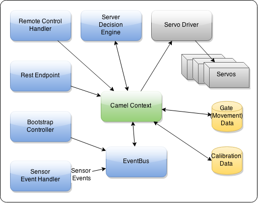
  • A need to integrate for control. I intend to have multiple ways of controlling the robot, via rest interface, by radio control and by the robot sending sensor info to a server to get instructions from the server. 
  • A need to integrate with persistence to read calibration and configuration data.
  • I use camel at my day job and figured it would be good to gain more experience with it using it in a different way.
  • I wanted to see if camel could run well on a raspberry pi.

Running Apache Camel on the Raspberry Pi

Camel can be run in number of different ways. It is most effective when it has a supporting dependency injection framework. In the past I've run it three different ways;
  • OSGI containers using Aries Blueprint
  • With Spring xml
  • Using Guice
  • Directly from java main.
Camel routes can be configured in via xml, however I never have like that approach even though many examples are provided that way. I prefer the Java dsl.
In my raspberry pi application I am using Apache Commons Configuration to abstract my configuration and Guice for dependency injection. I don't have any plans to run an OSGI container on the Pi so that rules our using blueprint. Spring was never on my list as an option so that leaves Guice and running from the Java main.

The obvious choice is Guice. I wanted to be able to use property placeholders in my routes. I like the flexibility of using them. What I wanted is the properties to resolve against the commons configuration since I am using configuration to encapsulate my config. I also needed beans to be bindable via guice and accessible in the camel registry. For example for the camel-guava-eventbus component. I'm using eventbus to provide a bus to allow different components to send events that I can react to and affect the  robots behavior. It gives me a more consistent way to manage the event processing.

Bridging between Commons Configuration, Guice and the Camel Registry

Camel has a guice component. It provides some excellent support. I would suggest it's the correct way to do this however I wanted to experiment with camel a bit more and decided just to roll my own camel context. One of the things I've learned about camel is there are many ways to solve each problem. So many in fact I'd recommend +Scott Cranton book the Apache Camel Developers Cookbook it helps you narrow down approaches to solving the types of real world integration problems you are likely to encounter. Since this is not a real world problem lets crack on (or should that be hack on).

Two problems to solve:
1. Property resolvers using Commons Configuration
2. Binding beans to the camel registry

Wednesday, March 25, 2015

Servo Abstraction for Raspberry Pi Java PWM Servo Driver


After getting the servo output in the last post (Raspberry Pi Java PCA9685 PWM Driver - First servo pulses output) and validating the output was reasonably accurate I had to look at the way I wanted to update the servo values. In the initial example in the previous post I was using a hard coded output.

My goal is some other part of the application will set a specific servos angle without caring about constraints such as range or calibration. To achieve this I added a new interface called Servo to provide access to information about specific servo instances. Originally I did not have this. It's absent in earlier UML in my blog. However I decided the servo was the best place to encapsulate servo calibration data. I want each part of the application to have the appropriate separation of concern. An overview of the abstraction I have currently is as follows.

  • Servo
    • Provides abstraction of individual servo data such as calibration data
    • Provides an interface to set the desired angle on  the servo
    • Methods to provide calibrated pulse length
  • Servo Driver
    • The servo driver provides methods to set the servo update frequency that al servos require
    • Methods to update the position of one or multiple servos
  • Comm Device
    • The device provides an interface for the actual communication device. 
    • The device handles the protocol for communication to the device (i2C in this case)
    • Actual Device is PCA9685 based device Adafruit PWM servo driver
  • Physical Servo
    • The actual servo

My goal is some other part of the application will set a specific servos angle without caring about constraints such as range or calibration. To achieve this I added a new interface called Servo to provide access to information about specific servo instances. Originally I did not have this. It's absent in earlier UML in my blog. However I decided the servo was the best place to encapsulate servo calibration data.

In this post I'll share what I have so far for the servo and servo driver.

Servo

Just as an example, different servos have different ranges. The typical RC servo pulse is 1ms to 2ms where 1ms is full left and 2ms is full right.  If a servo is 180 of range -90degs from center to 90 degs from center. A range of 120 is -60degs to 60degs.

I want to be able to interact with servos using degs of angle. This will be more practical for creating leg movement sequencing. I want to be able to set -60 and know the servo regardless of range will move to that angle. It actually would be 1ms pulse on a 120 deg servo but 1.33ms on a 180 deg servo.

With that in mind it made sense to encapsulate all the servo calibration data in the servo object. The calibration fields are
  1. range - the maximum range of the servo in total degrees.
  2. center - where the center of the servo is as installed. This depends on the installation and how the servo control arm/wheel is fitted on the servo. This calibration allows the tuning of the center position of the servo
  3. lowLimit - Limits the travel of the servo. In the robot the servo is constrained by the physical leg movement before it reaches its range of travel. The limit prevents damage to the servo.
  4. highLimit - same as above but for high

Therefore the servo should provide the pulse length pre calibrated with the calibration data above. Most of the methods are accessors to the calibration data fields. However the getPulseLength method is more interesting

    public int getPulseLength(int argAngle) {
        // limit angle
        if(argAngle > getHighLimit()){
            int newAngle = getHighLimit();
            LOGGER.trace("Angle exceeds high limit. Requested: {}, Using: {}", argAngle, newAngle);
            argAngle = newAngle;
        }
        if(argAngle < getLowLimit()){
            int newAngle = getLowLimit();
            LOGGER.trace("Angle exceeds low limit. Requested: {}, Using: {}", argAngle, newAngle);
            argAngle = newAngle;
        }
        double offset = getMicrosPerDeg() * (argAngle + getCenter());
        double mid = (MIN_PULSE + MAX_PULSE) / 2;
        int pulse = (int) Math.round(mid + offset);
        if (pulse < MIN_PULSE) {
            LOGGER.trace("specified angle exceeds minimum, returning minimum instead");
            pulse = MIN_PULSE;
        }
        if (pulse > MAX_PULSE) {
            LOGGER.trace("specified angle exceeds maximum, returning maximum instead");
            pulse = MAX_PULSE;
        }
        LOGGER.trace("Calculating pulse length for servo angle {}: {}\u00B5S", argAngle, pulse);
        return pulse;
    }

I created a fluent builder for the servo implementation object. This makes it nicer to create an instance of servo.

    private Servo getTestServo(){
        return new ServoImpl.Builder()
                .name("TestServo")
                .channel(0)
                .center(0)
                .build();
    }


This method returns the angle adjusted for the center and enforcing the limits. It also uses a helper method to get the number of microseconds per deg of angle for  servo with the range as set. The test case ServoImplTest is a good place to go see how the tests for this method work.

    @Test
    public void testGetPulseLength(){
        Servo servo = getTestServo();

        // TESTING CENTER
        LOGGER.info("Testing CENTER");
        servo.setAngle(0);
        assertPulse(servo, 1500);

This test tests if a servo with no center offset set to angle 0 returns the correct 1500ms pulse. There are test for different angles to test the range of options.

Servo Driver

The servo driver provides the interface between a servo and the actual servo. It has methods to update the servo position and to set the frequency. The implementation of the driver is specific to the Adafruit 16-Channel 12-bit PWM/Servo Driver . It could be reused for another PCA9685 device. 

Set PWMFrequency


    @Override
    public void setPulseFrequency(int frequency) throws IOException {
        LOGGER.info("Setting pwm frequency to {} hz", frequency);
        this.frequency = frequency;
        int prescale = getPreScale(frequency);

        LOGGER.debug("Reading value of Mode 1 register");
        int oldMode1 = device.readRegister(PCA9685Device.MODE1);
        LOGGER.debug("Mode 1 register: {}", Integer.toHexString(oldMode1));

        int newMode1 = (oldMode1 & 0x7F) | PCA9685Device.MODE1_SLEEP;
        LOGGER.debug("Setting sleep bit on Mode 1 register: {}", Integer.toHexString(newMode1));
        device.writeRegister(PCA9685Device.MODE1, (byte)newMode1);

        LOGGER.debug("Writing prescale register with: {}", Integer.toHexString(prescale));
        device.writeRegister(PCA9685Device.PRESCALE, (byte)prescale);

        newMode1 = oldMode1 & ~PCA9685Device.MODE1_SLEEP;
        LOGGER.debug("Writing the old value back to mode1 register with sleep off to start osc again: {}", Integer.toHexString(newMode1));
        device.writeRegister(PCA9685Device.MODE1, (byte)(newMode1));
        // wait for oscillator to restart
        sleep(50);
        newMode1 = oldMode1 | PCA9685Device.MODE1_RESTART;
        LOGGER.debug("Setting restart bit: {}", Integer.toHexString(newMode1));
        device.writeRegister(PCA9685Device.MODE1, (byte)newMode1);
    }

The set frequency method writes the value to the prescale register then restarts the PCA9685 oscillator to send Pulse Width Modulation (PWM) signals to the servos. Unit tests are provided to test the values sent to the register are correct. The set frequency calls the method getPreScale(frequency) to get the actual value. I've talked about that in a previous post. It's work looking at to see how the value is calculated. http://www.margic.com/2015/03/java-pca9685-pwm-driver-first-servo.html it's worth checking that out as it includes details on how to add a necessary correction factor that deviates from the PCA9685 datasheet.

Update Servo

This is the main method used to set a single servo's position in the java driver.

    @Override
    public void updateServo(Servo servo) throws IOException {
        // update cache first
        cacheServo(servo);
        int servoChannel = servo.getChannel();
        int pulseLength = servo.getPulseLength(servo.getAngle());

        // calc num counts for ms
        long count = Math.round(pulseLength * RESOLUTION / ((double)1 / (double)getPulseFrequency()) / (double)1000000);

        LOGGER.debug("Updating servo position: {}, count: {}", servo.toString(), count);

        byte[] offBytes = ByteUtils.get2ByteInt((int)count);
        device.writeRegister(getRegisterForChannel(servoChannel, Register.ON_LOW), (byte) 0x00);
        device.writeRegister(getRegisterForChannel(servoChannel, Register.ON_HIGH), (byte) 0x00);
        device.writeRegister(getRegisterForChannel(servoChannel, Register.OFF_LOW), offBytes[ByteUtils.LOW_BYTE]);
        device.writeRegister(getRegisterForChannel(servoChannel, Register.OFF_HIGH), offBytes[ByteUtils.HIGH_BYTE]);
    }

The updateServo method accepts a servo object. This was a driver behind creating the new servo interface for this update. It allows removing the dependency directly on the implementation. This method has to determine the number of counts out of the max resolution of 4096 that apply to a given servo position. For example if the desired PWM duty cycle is 50% (on for 50% of the time) at 50Hz refresh that would be 2048 counts. It's always 2048 for 50% cycle, however the actual time for the cycle depends on frequency. At 50Hz 100% cycle is 20ms in length at 100Hz it would be half that at 10ms. Therefore I measure servo PWM in length not duty cycle. As servo center should be 1.5ms regardless of frequency.

In the method I have a rather clumsy calculation for pulse length. I'll fix it later. However once again test case are provided to validate it does set the correct values to the PCA9685 registers.

Saturday, March 21, 2015

Raspberry Pi Java PCA9685 PWM Driver - First servo pulses output

It's now time to turn attention to the servo output channels on the Adafruit PCA9685 device. I haven't completed any of the logic to set the servo angle but wanted to check the Java driver for the Raspberry Pi was working as expected. I needed to send a test Pulse Width Modulation (PWM) signal to one of the out put channels.

Calculating the register settings for a test pulse

A servo pulse is repeated x times a second. The specific frequency is not critical it should be somewhere around 50Hz for a typical servo. What is important is the pulse length. At 50Hz the the entire cycle is 20ms. A servo pulse is some where between 1ms and 2ms. That's between 5% and 10% of the cycle. Given we only have a max of 10% of the PWM to play with any errors are going to be fairly significant.

The PCA9685 uses 2 pairs registers per channel to set the pulse. It has a resolution of 4096bits, thats why it takes a pair of 1byte registers to represent a value with maximum of 4096. The value represents a count of time in the cycle. The first pair represents when the output will be turned on, the second when the output will be turned off.

To determine the frequency a pre scaler is used to scale the PCA9685 internal oscillator from 25MHz to the appropriate value. At 25Mhz 4096 counts would be over way to fast 0.16ms incase your wondering. (Ok I admit thats not actually possible, in fact the actual max of the output is 1Khz) The goal is to get a the modulation frequency to close to 50Hz.

The datasheet provides the formula for setting the prescaler to provide the expected frequency:
prescaleVal = round(oscClock/(4096 * updateRate)) - 1

My Java driver includes a method to set the PWMFrequency

    public int getPreScale(int frequency) throws IOException{
        LOGGER.debug("Get prescale value for frequency {}", frequency);
        
        double prescaleval = CLOCK_FREQUENCY;
        prescaleval /= RESOLUTION;
        prescaleval /= frequency;
        prescaleval -= 1.0;
        LOGGER.debug("Estimated pre-scale {}", prescaleval);
        prescaleval = Math.round(prescaleval + 0.5);

        if(prescaleval > 254){
            throw new IOException("Specified frequency " + frequency + " results in prescale value " + prescaleval + " that exceed limit 254");
        }
        int prescale = (int)prescaleval;
        LOGGER.debug("Final pre-scale {}", prescale);
        return prescale;
    }

To test this I needed to request to send known output to the output channel.
If the resolution is 4096 the time for that amount of counts is 20ms it simply 4096/20 = 204.8 to figure out how many counts represent a 1ms pulse, 1ms being the lowest servo pulse. I happened to round down to 204 or 0xCCh cause it was neater and is insignificant. I hard coded these to set the registers.

        try {
            device.writeRegister(PCA9685Device.LED0_ON_HIGH, (byte) 0x00);
            device.writeRegister(PCA9685Device.LED0_ON_LOW, (byte) 0x00);
            device.writeRegister(PCA9685Device.LED0_OFF_HIGH, (byte) 0x00);
            device.writeRegister(PCA9685Device.LED0_OFF_LOW, (byte)0xCC);
        }catch(IOException ioe){
            LOGGER.error("Error setting pulse", ioe);
        }


The four registers are set for LED0 (channel 0) the first two specify the count when it should turn on. This is set to 0 counts. The pulse will begin at the start of each cycle. 204 is less than 255 so the off high byte is 0 with 204(0xCCh) in the off low byte.
I hooked up the pocket scope to see what the output was. I was a bit surprise to see that the trace did not measure a full second. It's somewhere around 950µs. I wasn't expecting it to be off by that much.

I looked at a lot of sample code before starting my own driver. I had actually written some python code based on some example. I remember seeing one a comment in the code about some correction factor for the PCA9685. Turns out cyanogilvie on github reported an issues to adafruit Frequency accuracy issue

In that issue he reported that a correction factor of 0.9 on the frequency does the trick.

        double correctedFrequency = frequency * 0.9;  // Correct for overshoot in the frequency setting (see issue #11).
        double prescaleval = CLOCK_FREQUENCY;
        prescaleval /= RESOLUTION;
        prescaleval /= correctedFrequency;

With that correction I get the output below. Now it's much closer. It's still not perfect but it's within acceptable tolerances for my purpose now.

I had significant doubts that a $50 scope would be useful enough. I had read other people were looking to use it for measuring servo inputs. At least I can confirm its of some utility for that purpose.

I did not measure how close the cycle is to 50Hz as I mentioned it is not that important. The key factor is the pulse length.

I would recommend adding this correction. I have seen a lot of code out there that does not use this correction. At least I and two others have measured the output can validate it with these parameters.


Thursday, March 19, 2015

Creating a Java Driver for the Adafruit PCA9685 PWM Driver

The hex robot is going to have a large number of servos, 3 per leg total of 18 servos. I needed a way to drive that many servos from the Raspberry Pi. I ended up buying a couple of Adafruit's rather cool little breakout boards the Adafruit 16-Channel 12-bit PWM/Servo Driver - I2C interface - PCA9685


This little board is based around a NXP Semiconductors PCA9685 chip and is supports an I2C interface. The chip does the hard work of outputting servo pwm signals that will work well with RC Style servos. It's designed for LEDs but so far it works just as well with Servos. I suspect I will have to beef up the power delivery for running all the servos.

Adafruit has some good examples on how to use this board with the Raspberry Pi check the product page for links or Adafruit's Github for the python examples.

I started working on Java driver for the board. I wanted the design of the driver to support unit testing in my application and have just finished creating the framework for the driver. As this is a work in progress the code for the driver is still part of my main project. Once I have got it more stable I'll separated it if any one expresses any interest in contributing to it. Until then it's likely to continue to evolve as I explore the functionality.

The main concern I had was using the Pi4J library for I2C communication has a dependency on Pi4J native libraries. These wouldn't build in maven for me due to the missing native libraries. If your trying to build in maven with the Pi4J library you'll probably need to exclude the native libraries unless you have them installed.
        
            com.pi4j
            pi4j-core
            ${pi4j.version}
            
                
                    com.pi4j
                    pi4j-native


The goal for creating the Java driver was to ensure I could run unit tests without the native libraries present.


Driver Classes


I wanted the ServoDriver interface to abstract the rest of the application code from the driver implementation. The driver provides methods for setting the angle of a servo and the frequency of refresh.
The PCA9685Device abstracts the read write operations of the device as well as providing all the register constants for the device.
The AdafruitServoDriver provides the servo driver higher level functions for providing the sequencing of reads and writes to initialize and interact with the device via a Device implementation. There are some settings that have to be set that the servo driver implementation encapsulates. For example the PRE_SCALE register defines the frequency at which the outputs modulate. The prescale value is determined with the formula shown

prescaleVal = round(oscClock/(4096 * updateRate)) - 1
Example assuming 25MHz the modulation frequency of 200 Hz
prescaleVal = round(25000000 / (4096 * 200)) - 1 = 30

In my case the frequency is 50Hz, this is fairly average frequency for RC Servos. The driver can be configured via a property. (The example of 200Hz is provided in the PCA9685 data sheet incase your wondering why. It was a good known good example to test)

The Device interface provides lower level read/write operations for interacting with the device registers. When using netbeans and running on the Raspberry Pi directly it is easier to test agains the actual board itself. However I wanted to be able to test my code in unit tests. To enable this I create a MockPCA9685Device that very simply provides a set of registers that one can use in unit tests to check the registers are being set correctly.

For example in my ServoDriverTest I initialize the servo driver as follows

    
@Before
    public void setUpServoDriver() {
        try {
            this.configuration = new PropertiesConfiguration("com.margic.pihex.properties");
        }catch(ConfigurationException ce){
            LOGGER.error("Failed to get properties.", ce);
        }
        mockDevice = new MockPCA9685Device();
        this.driver = new AdafruitServoDriver(configuration, mockDevice);
    }

You can see that the AdafruitServoDriver is constructed with the mock device. In the actual code the real device can be provided in the construct or can be injected using dependency injection.

The following test tests setting the PWM frequency. This involves setting the PRESCALE register in the PCA9685 device. Register 0xFE if your interested. For my default 50Hz this register should be set to the value 121 (0x79). This would be difficult to test in a unit test as viewing the registers is not easy. The mockdevice helps. The following test test setting the frequency to a few different values and reads the value from the device to assert the register is set correctly to the correct PRESCALE value (disclaimer: I'm stating the are the correct values, but to be honest I haven't validated them yet)

 
    @Test
    public void testSetPWMFrequency() throws IOException{
        driver.setPWMFrequency(50);
        mockDevice.dumpRegisters();
        assertEquals(121, mockDevice.readRegister(PCA9685Device.PRESCALE));

        driver.setPWMFrequency(200);
        mockDevice.dumpRegisters();
        assertEquals(30, mockDevice.readRegister(PCA9685Device.PRESCALE));

        driver.setPWMFrequency(30);
        mockDevice.dumpRegisters();
        assertEquals(202, mockDevice.readRegister(PCA9685Device.PRESCALE));

        mockDevice.dumpByteStream();
    }

After each test dumpRegisters is called to display the registers. This is just for convenience. Personally I like to be able to visually inspect the values at this point of the development. The output of the test looks like below.

[main] DEBUG com.margic.adafruitpwm.AdafruitServoDriver - Creating new servo driver Adafruit-PCA9685 for device Mock PCA9685 device
[main] DEBUG com.margic.adafruitpwm.AdafruitServoDriver - Setting pwm frequency to 50 hz
[main] DEBUG com.margic.adafruitpwm.AdafruitServoDriver - Read MODE 1 Register
[main] DEBUG com.margic.adafruitpwm.AdafruitServoDriver - Get prescale value for frequency 50
[main] DEBUG com.margic.adafruitpwm.AdafruitServoDriver - Estimated pre-scale 121.0703125
[main] DEBUG com.margic.adafruitpwm.AdafruitServoDriver - Final pre-scale 121
[main] DEBUG com.margic.adafruitpwm.AdafruitServoDriver - Reading value of Mode 1 register
[main] DEBUG com.margic.adafruitpwm.AdafruitServoDriver - Mode 1 register 0
[main] DEBUG com.margic.adafruitpwm.AdafruitServoDriver - Setting sleep bit on Mode 1 register 10
[main] DEBUG com.margic.adafruitpwm.AdafruitServoDriver - Writing prescale register with 121
[main] DEBUG com.margic.adafruitpwm.AdafruitServoDriver - Writing the old value back to mode1 register to start osc again
[main] INFO com.margic.adafruitpwm.mock.MockPCA9685Device - Registers:
00000000 80 00 00 00 00 00 00 00 00 00 00 00 00 00 00 00 ................
00000010 00 00 00 00 00 00 00 00 00 00 00 00 00 00 00 00 ................
00000020 00 00 00 00 00 00 00 00 00 00 00 00 00 00 00 00 ................
00000030 00 00 00 00 00 00 00 00 00 00 00 00 00 00 00 00 ................
00000040 00 00 00 00 00 00 00 00 00 00 00 00 00 00 00 00 ................
00000050 00 00 00 00 00 00 00 00 00 00 00 00 00 00 00 00 ................
00000060 00 00 00 00 00 00 00 00 00 00 00 00 00 00 00 00 ................
00000070 00 00 00 00 00 00 00 00 00 00 00 00 00 00 00 00 ................
00000080 00 00 00 00 00 00 00 00 00 00 00 00 00 00 00 00 ................
00000090 00 00 00 00 00 00 00 00 00 00 00 00 00 00 00 00 ................
000000A0 00 00 00 00 00 00 00 00 00 00 00 00 00 00 00 00 ................
000000B0 00 00 00 00 00 00 00 00 00 00 00 00 00 00 00 00 ................
000000C0 00 00 00 00 00 00 00 00 00 00 00 00 00 00 00 00 ................
000000D0 00 00 00 00 00 00 00 00 00 00 00 00 00 00 00 00 ................
000000E0 00 00 00 00 00 00 00 00 00 00 00 00 00 00 00 00 ................
000000F0 00 00 00 00 00 00 00 00 00 00 00 00 00 00 79 00 ..............y.

[main] DEBUG com.margic.adafruitpwm.AdafruitServoDriver - Setting pwm frequency to 200 hz
[main] DEBUG com.margic.adafruitpwm.AdafruitServoDriver - Read MODE 1 Register
[main] DEBUG com.margic.adafruitpwm.AdafruitServoDriver - Get prescale value for frequency 200
[main] DEBUG com.margic.adafruitpwm.AdafruitServoDriver - Estimated pre-scale 29.517578125
[main] DEBUG com.margic.adafruitpwm.AdafruitServoDriver - Final pre-scale 30
[main] DEBUG com.margic.adafruitpwm.AdafruitServoDriver - Reading value of Mode 1 register
[main] DEBUG com.margic.adafruitpwm.AdafruitServoDriver - Mode 1 register 80
[main] DEBUG com.margic.adafruitpwm.AdafruitServoDriver - Setting sleep bit on Mode 1 register 10
[main] DEBUG com.margic.adafruitpwm.AdafruitServoDriver - Writing prescale register with 30
[main] DEBUG com.margic.adafruitpwm.AdafruitServoDriver - Writing the old value back to mode1 register to start osc again
[main] INFO com.margic.adafruitpwm.mock.MockPCA9685Device - Registers:
00000000 80 00 00 00 00 00 00 00 00 00 00 00 00 00 00 00 ................
00000010 00 00 00 00 00 00 00 00 00 00 00 00 00 00 00 00 ................
00000020 00 00 00 00 00 00 00 00 00 00 00 00 00 00 00 00 ................
00000030 00 00 00 00 00 00 00 00 00 00 00 00 00 00 00 00 ................
00000040 00 00 00 00 00 00 00 00 00 00 00 00 00 00 00 00 ................
00000050 00 00 00 00 00 00 00 00 00 00 00 00 00 00 00 00 ................
00000060 00 00 00 00 00 00 00 00 00 00 00 00 00 00 00 00 ................
00000070 00 00 00 00 00 00 00 00 00 00 00 00 00 00 00 00 ................
00000080 00 00 00 00 00 00 00 00 00 00 00 00 00 00 00 00 ................
00000090 00 00 00 00 00 00 00 00 00 00 00 00 00 00 00 00 ................
000000A0 00 00 00 00 00 00 00 00 00 00 00 00 00 00 00 00 ................
000000B0 00 00 00 00 00 00 00 00 00 00 00 00 00 00 00 00 ................
000000C0 00 00 00 00 00 00 00 00 00 00 00 00 00 00 00 00 ................
000000D0 00 00 00 00 00 00 00 00 00 00 00 00 00 00 00 00 ................
000000E0 00 00 00 00 00 00 00 00 00 00 00 00 00 00 00 00 ................
000000F0 00 00 00 00 00 00 00 00 00 00 00 00 00 00 1E 00 ................

[main] DEBUG com.margic.adafruitpwm.AdafruitServoDriver - Setting pwm frequency to 30 hz
[main] DEBUG com.margic.adafruitpwm.AdafruitServoDriver - Read MODE 1 Register
[main] DEBUG com.margic.adafruitpwm.AdafruitServoDriver - Get prescale value for frequency 30
[main] DEBUG com.margic.adafruitpwm.AdafruitServoDriver - Estimated pre-scale 202.45052083333334
[main] DEBUG com.margic.adafruitpwm.AdafruitServoDriver - Final pre-scale 202
[main] DEBUG com.margic.adafruitpwm.AdafruitServoDriver - Reading value of Mode 1 register
[main] DEBUG com.margic.adafruitpwm.AdafruitServoDriver - Mode 1 register 80
[main] DEBUG com.margic.adafruitpwm.AdafruitServoDriver - Setting sleep bit on Mode 1 register 10
[main] DEBUG com.margic.adafruitpwm.AdafruitServoDriver - Writing prescale register with 202
[main] DEBUG com.margic.adafruitpwm.AdafruitServoDriver - Writing the old value back to mode1 register to start osc again
[main] INFO com.margic.adafruitpwm.mock.MockPCA9685Device - Registers:
00000000 80 00 00 00 00 00 00 00 00 00 00 00 00 00 00 00 ................
00000010 00 00 00 00 00 00 00 00 00 00 00 00 00 00 00 00 ................
00000020 00 00 00 00 00 00 00 00 00 00 00 00 00 00 00 00 ................
00000030 00 00 00 00 00 00 00 00 00 00 00 00 00 00 00 00 ................
00000040 00 00 00 00 00 00 00 00 00 00 00 00 00 00 00 00 ................
00000050 00 00 00 00 00 00 00 00 00 00 00 00 00 00 00 00 ................
00000060 00 00 00 00 00 00 00 00 00 00 00 00 00 00 00 00 ................
00000070 00 00 00 00 00 00 00 00 00 00 00 00 00 00 00 00 ................
00000080 00 00 00 00 00 00 00 00 00 00 00 00 00 00 00 00 ................
00000090 00 00 00 00 00 00 00 00 00 00 00 00 00 00 00 00 ................
000000A0 00 00 00 00 00 00 00 00 00 00 00 00 00 00 00 00 ................
000000B0 00 00 00 00 00 00 00 00 00 00 00 00 00 00 00 00 ................
000000C0 00 00 00 00 00 00 00 00 00 00 00 00 00 00 00 00 ................
000000D0 00 00 00 00 00 00 00 00 00 00 00 00 00 00 00 00 ................
000000E0 00 00 00 00 00 00 00 00 00 00 00 00 00 00 00 00 ................
000000F0 00 00 00 00 00 00 00 00 00 00 00 00 00 00 CA 00 ................

[main] INFO com.margic.adafruitpwm.mock.MockPCA9685Device - ByteStream:
00000000 10 79 00 80 10 1E 80 80 10 CA 80 80             .y..........


Process finished with exit code 0

The next steps are to work on the actual servo registers and better defining the servo driver interface. Once thats done I'm looking forward to checking out the output on the pocket oscilloscope I mentioned in my previous post pocket-oscilloscope-for-measuring-pwm

I'll post some examples and some sample outputs when that part works.

Tuesday, March 17, 2015

Deploying jar to Raspberry Pi Using Intellij and Maven

I decided to switch from python to java for the Raspberry Pi controller for the robot. I wanted to see how good Java on the pi is not that Oracle are releasing proper JVM support for the Raspberry Pi ARM Processors.

I ran the first few hello world examples in Netbeans. I was really impressed with the remote platform. However I didn't want to use ant and netbeans. I wanted to use Intellij and Maven for developing and building the code for the Raspberry Pi.

The remote platform support (Netbeans Howto incase your interested) in Netbeans is excellent for working with the Raspberry Pi but as the project grows I want to stick with my familiar world.

I had three problems to solve;
  1. How to package the dependencies into an executable jar for deployment onto the Pi
  2. Deploying the built jar to the Pi
  3. Remote running and debugging the code on the pi.
For now I have got an acceptable answer to the first two. Number three will have to wait until it gets on my nerves more.

1. Packaging dependencies

I decided the simplest way to do this would be to use the maven shade plugin in my pom file. 

Maven Shade plugin in pom file:
            
                org.apache.maven.plugins
                maven-shade-plugin
                ${shade.version}


                            com.margic.pihex.PiHex


                        package
                        
                            shade


Notice the transformer starting at line 7. This sets the main class in the manifest to make this an executable jar file. The shade plugin grabs all the transient dependencies and packages them in the jar file for you.

2. Deploying the built jar on the Raspberry Pi

This is a bit of a cheat for getting the jar file on the pi. I'm sure there are better ways and creating a remote runtime tool would be better but for this phase of development it makes it super easy for me just to run maven:install and the jar is shaded as above then copied to the pi using antrun tasks. First the task creates the folder specified if it doesn't exist then copies the build single executable jar to the pi using scp. Very convenient for simple testing.


                org.apache.maven.plugins
                maven-antrun-plugin
                ${antrun.version}
                
                    
                        install


                            run


                        org.apache.ant
                        ant-jsch
                        1.9.4


Now the code is on the pi I still have to run it on the pi. But this is much simpler as it's now just one command

pi@raspberrypi ~ $ java -jar /home/pi/pihex/pihexj-1.0-SNAPSHOT.jar
[main] INFO com.margic.pihex.PiHex - Starting PiHex application
[main] DEBUG com.margic.adafruitpwm.AdafruitServoDriver - Creating new servo driver Adafruit-PCA9685
pi@raspberrypi ~ $ 

Thursday, March 12, 2015

Servo Testing

Servo Test Rig Diagram
The first task was to check if I could control the servos with the Adafruit controller. There is a example code on their website. I started with that and simplified it a little bit.

One the main problems I found is that the python-smbus required to communicate with the i2c protocol on the Adafruit controller was just note Windows friendly. I ended up using VM Ware player with a Debian distribution like the Raspberry Pi. This was more effective as it has the supporting libraries used by the python-smbus package.


Servo Test Photo


Pocket oscilloscope for measuring rc servo pwm

It's been some time since I looked at the robot. A few things have changed. I'll comment on them later. But first, one of the troubles I had was determining if the servo signals my Pulse Width Modulation (PWM) board was putting out were correct.

I had been looking for servo testers etc in the RC hobby world and couldn't find any. It looked like getting an expensive oscilloscope was going to be the only way to solve this problem. I checked usual places for used equipment. The cost was crazy. This is supposed to be a cheap fun project.

I stumbled upon this little device. It's a pocket Oscilloscope selling on Amazon for around $50.

So far so good. In the picture you can see the signal being sent of approx 1.5ms knowing pwm servo signals vary from 1 to 2ms this looks reasonable for a center position. You can change the timebase of course and get a better signal view. I'm impressed. Solved the problem. At least now I can see if my code is sending out what I expect.


My PWM controller is the Adafruit 16-Channel 12-bit PWM/Servo Driver - I2C interface - PCA9685. I had hoped that I could use the scope for also monitoring the I2C interface. Now that java is supported better on the Raspberry pi (I'll talk about that in another post) I thought I would see how effective it would be to write the code in Java since that's my daily language. That means creating a java PWM library for the Adafruit controller. It would be good to be able to test that out with the pocket scope. However since it can only handle one trace at a time it's not possible to monitor both I2C signals.


General Servo pulse ranges.